OT/IT Network Segmentation and Isolation Design Guide
A comprehensive engineering blueprint for secure isolation and controlled interconnection between Operational Technology (OT) and Information Technology (IT) networks. Covering manufacturing, energy, building automation, rail transit, and water/wastewater environments.
System Overview
This OT–IT Network Isolation Design Guide provides an implementable engineering blueprint for secure isolation and controlled interconnection between Operational Technology (OT) networks and Information Technology (IT) networks. It is intended for environments that operate industrial control systems (ICS) and cyber-physical processes: factory production lines, energy generation and distribution, building automation, rail transit signaling and auxiliary control, and water/wastewater treatment. The guide covers deployments containing PLCs, RTUs, DCS controllers, SCADA servers, historians, engineering workstations, operator HMIs, industrial IoT gateways, and the supporting infrastructure including industrial Ethernet, fieldbus gateways, time synchronization, and management planes.
The scope and boundaries of this guide define OT and IT boundaries, partition OT into multiple zones, and design the OT–IT interface through isolation levels including physical isolation, logical isolation, unidirectional transfer, and DMZ-based controlled interconnect. It addresses both data flows (telemetry, historian replication, reporting) and control/maintenance flows (vendor support, engineering changes, remote diagnostics) with governing principles: business continuity first, minimum interconnection, zoning and conduits, deny by default, and auditable and operable.
The guide delivers a complete design package with diagrams, IP/VLAN plans, whitelist rule tables, DMZ service catalogs, commissioning test plans, and operational runbooks — ready for procurement, implementation, acceptance, and long-term operation. Key compliance drivers include IEC 62443, NIST SP 800-82, and ISO 27001 controls mapping.
System Architecture
The reference architecture establishes a layered defense model with the IT domain on one side, the OT domain on the other, and the Industrial DMZ serving as the controlled buffer zone between them. All cross-domain communication must traverse the dual-firewall DMZ structure, with optional unidirectional gateways (data diodes) for telemetry-only export paths. The O&M Access Zone provides a separate, audited channel for remote maintenance operations.
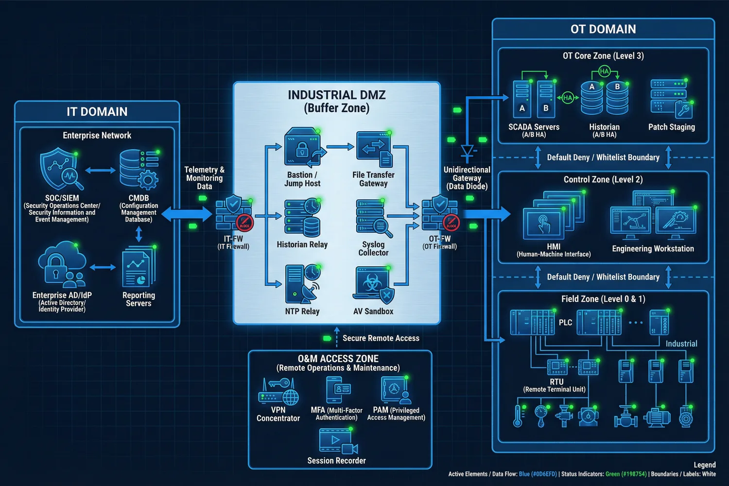
Figure 0.1: Overall OT–IT Isolation Reference Architecture — showing IT Domain, Industrial DMZ buffer zone, OT Domain zones (Field/Control/Core), O&M Access Zone, and all cross-domain data flows with Default Deny / Whitelist enforcement.
The architecture enforces a strict separation of responsibilities across five layers. The IT domain provides enterprise services, SOC operations, reporting, and identity providers, but never exercises direct control over OT assets. The Industrial DMZ acts as the termination point for all cross-domain services, performing protocol breaks, content inspection, file transfer control, and access brokering. The OT Core zone hosts site supervisory services and data aggregation. The Control Zone protects human-machine interfaces and engineering tools. The Field Zone contains controllers and devices with minimized services and reduced routable exposure.
| Layer | Primary Responsibility | Key Assets | Security Posture |
|---|---|---|---|
| IT Domain | Enterprise services, SOC, reporting, identity | SIEM, IdP, CMDB, Reporting | Standard IT security controls |
| Industrial DMZ | Cross-domain service termination, inspection, brokering | Firewalls, Bastion, File GW, Collectors | Dual-firewall, deny-by-default |
| OT Core Zone | Supervisory aggregation, OT management | SCADA, Historian, Patch Staging | Strict inbound control, monitored |
| Control Zone | HMI/EWS operations, engineering changes | HMI, Engineering Workstation | Highest protection, change control |
| Field Zone | Process control, I/O, sensing | PLC, RTU, IED, Sensors | Minimize services, protect integrity |
Main Functions
The OT–IT isolation framework encompasses eight core functional domains, each addressing a critical aspect of secure industrial network design. Together, these functions provide comprehensive coverage from initial asset baselining through ongoing operational assurance, ensuring that security controls are both effective and operationally sustainable.
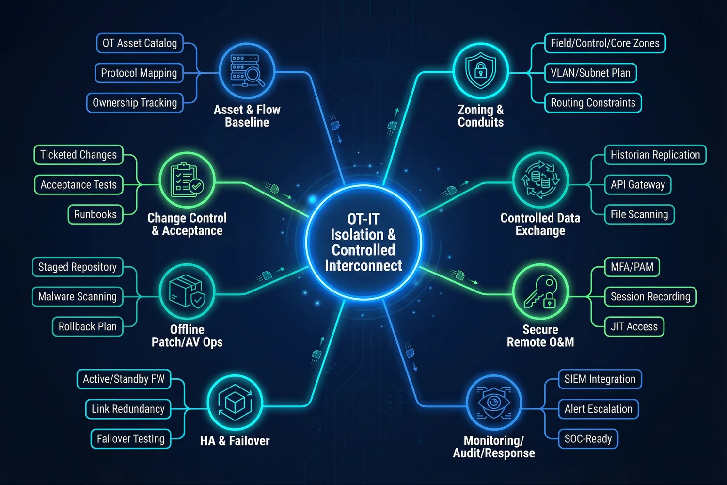
Figure 0.2: Main Functions Overview — eight core functional domains of the OT–IT isolation framework, from Asset & Flow Baseline through Change Control & Acceptance.
| Function | Value Delivered | Key Implementation | Acceptance Focus |
|---|---|---|---|
| Asset & Flow Baseline | Prevents unknown connectivity and shadow routes | OT/IT asset catalog, protocol mapping, ownership | 100% boundary links identified |
| Zoning & Conduit Design | Limits blast radius; enables least-privilege rules | OT zones, DMZ, O&M zone; VLAN/subnet plan | Inter-zone traffic via defined conduits only |
| Isolation Level Selection | Matches risk and operational need precisely | Decision matrix by directionality and safety impact | Isolation level justified per interconnect |
| Whitelist & DPI | Blocks lateral movement and unsafe commands | Application whitelists, industrial protocol DPI | Asset-pair-based ruleset; DPI alarms validated |
| Secure Remote O&M | Enables maintenance without exposing OT | PAM, MFA, JIT access, session recording | No direct VPN-to-OT; all sessions recorded |
| Offline Patch/AV Ops | Reduces malware risk without breaking uptime | Staged repository, scanning, maintenance window | Patch pipeline documented; hotfix path controlled |
| Logging, Audit & SOC | Detects abnormal OT traffic and unauthorized access | Syslog collectors, time sync, SIEM integration | Log completeness and alert tests pass |
| HA & Failover | Boundary security is not a single point of failure | HA firewalls, redundant links, failover testing | Failover within target RTO; no fail-open |