Scenarios & Selection
Chapter 3 — Eight real-world deployment scenarios with technical specifications, selection criteria, and design recommendations
3.1 Scenario Overview and Selection Framework
OT–IT isolation design requirements vary significantly across industry verticals and operational contexts. The appropriate isolation level, zone architecture, and technology selection depend on the specific combination of safety criticality, regulatory requirements, operational continuity constraints, and data flow patterns present in each environment. This chapter presents eight representative deployment scenarios drawn from the most common industrial sectors, each with a real-world deployment image, detailed technical description, and key performance indicators that guide design and procurement decisions.
The selection framework applies three primary dimensions to each scenario: the safety impact of a control system compromise (ranging from equipment damage to human safety risk), the operational continuity requirement (whether the process can tolerate any interruption), and the data exchange pattern (volume, frequency, and directionality of OT–IT data flows). These three dimensions together determine the recommended isolation level and the minimum required capabilities of the boundary devices.
| Scenario | Industry | Safety Impact | Continuity Req. | Recommended Isolation Level |
|---|---|---|---|---|
| S1: Discrete Manufacturing | Manufacturing | Medium (equipment damage) | High (production loss) | Industrial DMZ + OT Firewall + DPI |
| S2: Power Substation | Energy | Very High (grid stability) | Very High (24×7) | Dual Firewall DMZ + Data Diode option |
| S3: Building Automation | Facilities | Low–Medium | Medium | Logical Isolation + DMZ + Firewall |
| S4: Water Treatment | Utilities | High (public health) | High | Industrial DMZ + OT Firewall + IDS |
| S5: Rail Transit | Transportation | Very High (passenger safety) | Very High | Physical/Logical Isolation + DMZ |
| S6: Oil & Gas Pipeline | Energy | Very High (explosion risk) | Very High | Data Diode + SIS Separation + DMZ |
| S7: Pharmaceutical Mfg. | Life Sciences | High (product quality) | High (batch integrity) | DMZ + Validated FW + Audit Trail |
| S8: Data Center Facilities | IT Infrastructure | Medium (service outage) | High (SLA) | Logical Isolation + DMZ + Monitoring |
3.2 Scenario 1: Discrete Manufacturing
S1 — Discrete Manufacturing Production Line
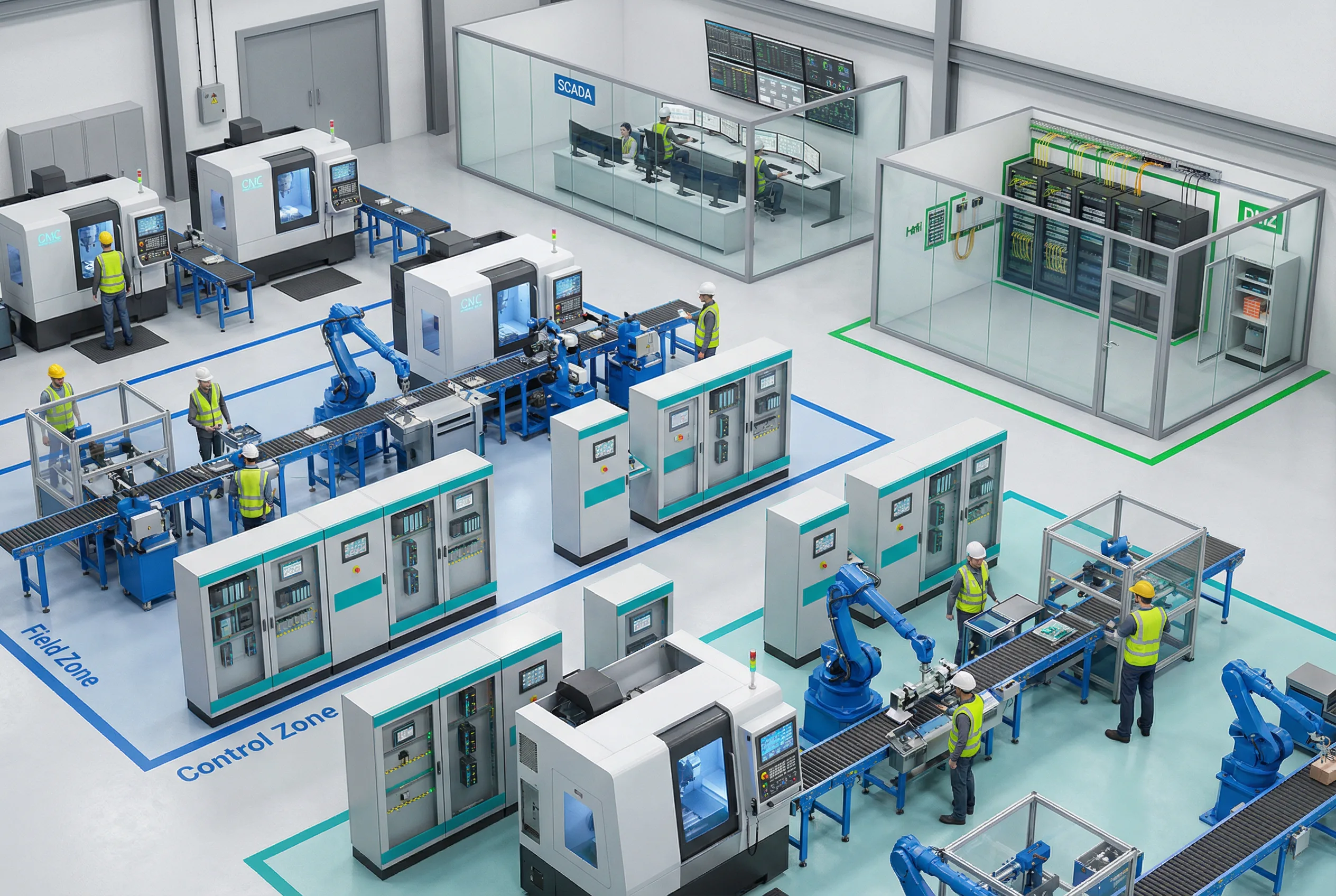
Figure 3.1: Discrete Manufacturing — Factory floor with Field Zone (PLCs, robots, CNC), Control Zone (HMI/EWS), OT Core (SCADA room), and DMZ cabinet. Color-coded zones illustrate the layered defense model.
Discrete manufacturing environments contain multiple production lines, each with PLCs, robotic cells, CNC machines, and conveyor systems. The Control Zone hosts HMI workstations and engineering tools that communicate with field devices via industrial Ethernet (PROFINET, EtherNet/IP). The OT Core SCADA server aggregates production data and feeds the MES/ERP systems in the IT domain through the DMZ historian relay. The primary security challenge is the high frequency of engineering changes, vendor support sessions, and software updates, all of which must be channeled through controlled pathways without disrupting production.
Key Design Considerations: The DPI engine must support both PROFINET and EtherNet/IP protocol inspection to enforce command-level whitelists. Engineering workstations require strict change control — all remote EWS sessions must terminate at the bastion. The MES integration path must use a historian relay in the DMZ, not a direct database connection. Patch staging must accommodate both Windows-based HMI/SCADA and embedded PLC firmware updates through the scanning gateway.
3.3 Scenario 2: Power Substation
S2 — Electrical Power Substation Control
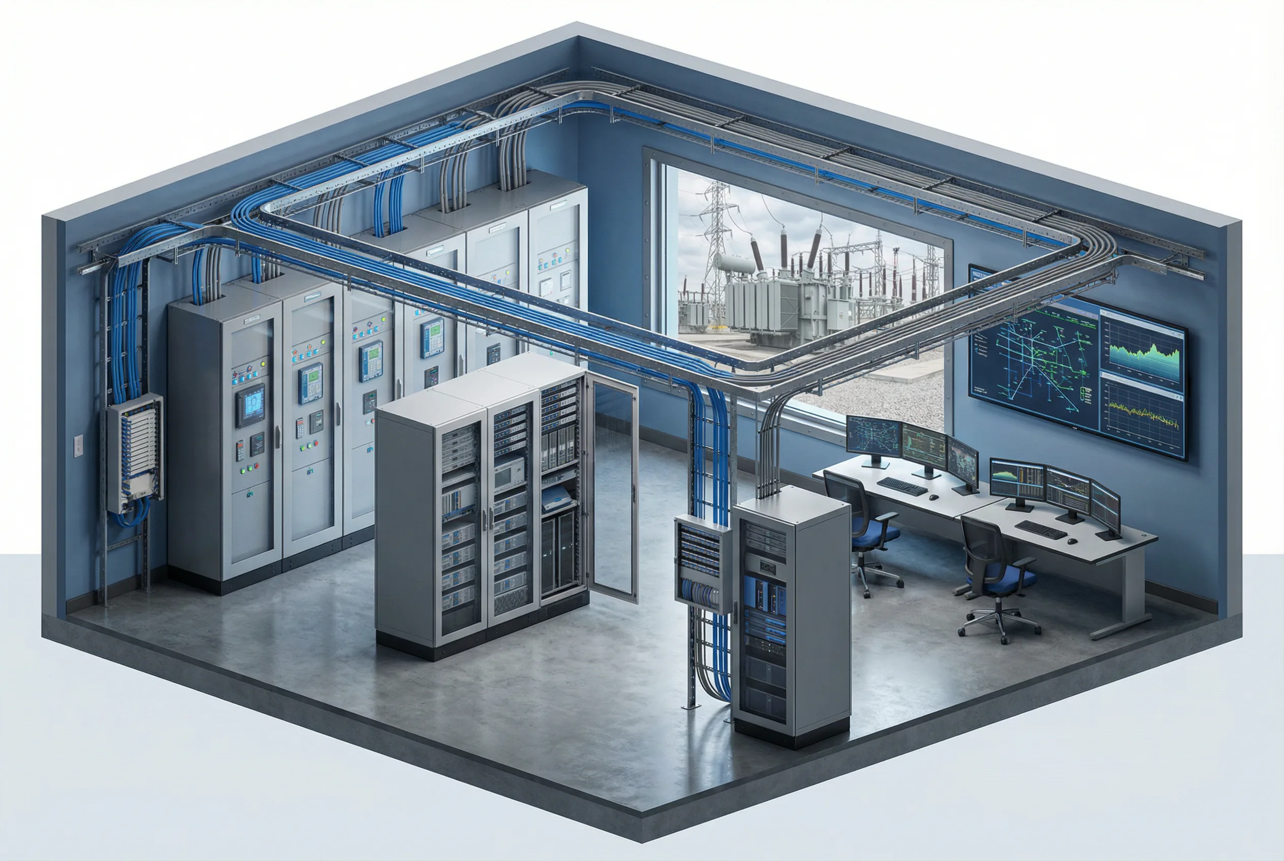
Figure 3.2: Power Substation — Control house with IED protection relay panels, RTU equipment, station control server, fiber distribution frame, and DMZ cabinet. Outdoor high-voltage equipment visible through window.
Power substations operate protection and control systems that must respond within milliseconds to fault conditions. The station LAN connects IEDs (Intelligent Electronic Devices) using IEC 61850 GOOSE and Sampled Values protocols, which are time-critical and cannot tolerate deep packet inspection latency. The RTU communicates with the SCADA master using IEC 60870-5-104 or DNP3 over WAN links. The primary security concern is that any disruption to protection functions could result in grid instability or equipment damage. A unidirectional gateway (data diode) is strongly recommended for the telemetry export path to the enterprise network, ensuring that no inbound path exists to the station LAN.
Key Design Considerations: GOOSE and SV traffic must remain entirely within the station LAN and must never traverse the DMZ. The data diode placement must be on the RTU/SCADA telemetry path only. The DMZ must support IEC 60870-5-104 and DNP3 inspection for the WAN SCADA path. Time synchronization is critical — the NTP/PTP relay must maintain sub-microsecond accuracy for IED timestamping. Bypass switches, if present, must be physically locked and require dual-person authorization.
3.4 Scenario 3: Building Automation
S3 — Building Automation System (BAS/BMS)
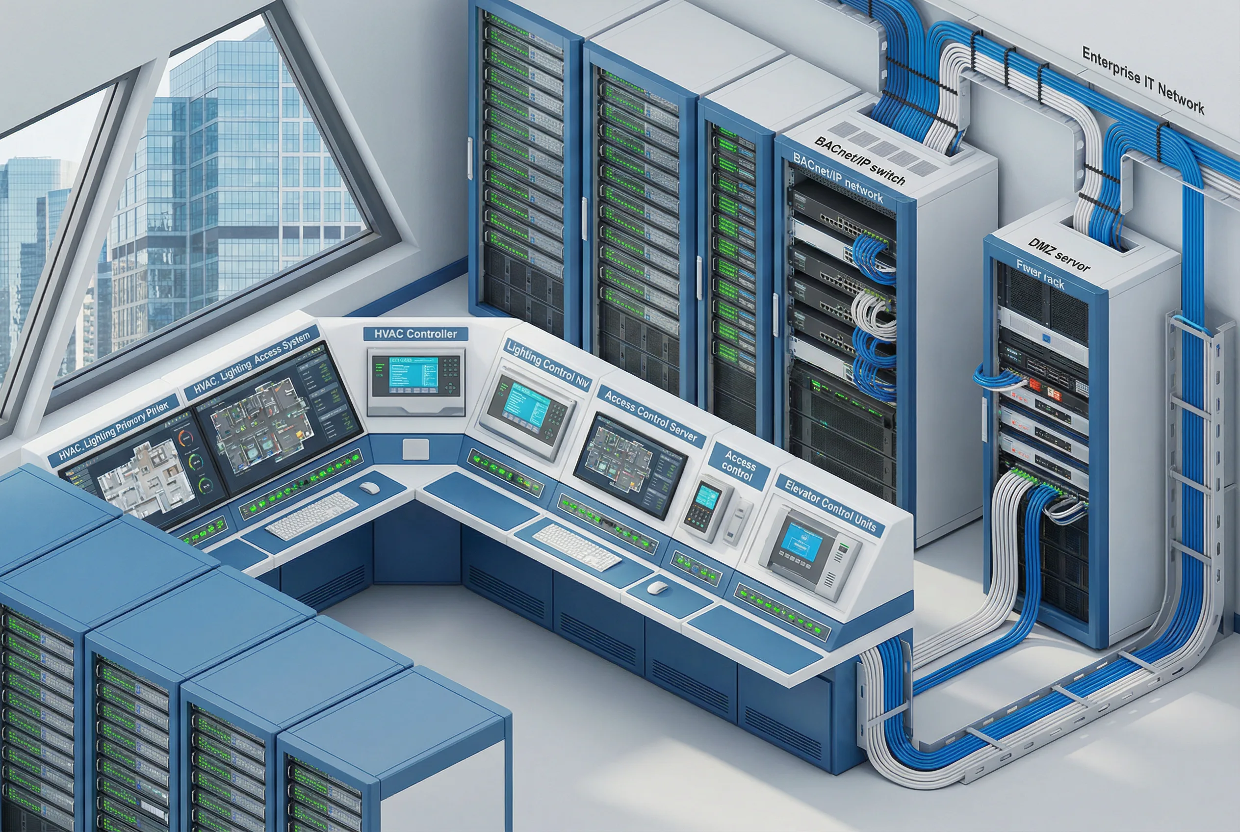
Figure 3.3: Building Automation — BMS control room with HVAC controllers, lighting control, access control servers, elevator control units, BACnet/IP network switches, and DMZ firewall rack connecting to enterprise IT network.
Building automation systems integrate HVAC, lighting, access control, elevators, fire suppression, and energy management into a unified BMS platform. These systems increasingly use IP-based protocols (BACnet/IP, Modbus TCP) and are connected to enterprise IT networks for energy reporting and tenant management. The security challenge is that BAS systems are often managed by facilities contractors who require remote access, and the building network may share physical infrastructure with the corporate IT network. Logical isolation using VLANs and a dedicated firewall is the minimum requirement, with a full DMZ recommended for larger facilities or those with sensitive tenants.
Key Design Considerations: BACnet/IP broadcast traffic must be contained within the BAS VLAN and must not propagate to the IT network. Access control systems require careful separation — the physical access database may need to be replicated to IT HR systems, but this must occur through a controlled API gateway in the DMZ, not a direct database link. Facilities contractor remote access must be channeled through the O&M zone with session recording.
3.5 Scenario 4: Water Treatment
S4 — Water and Wastewater Treatment Plant
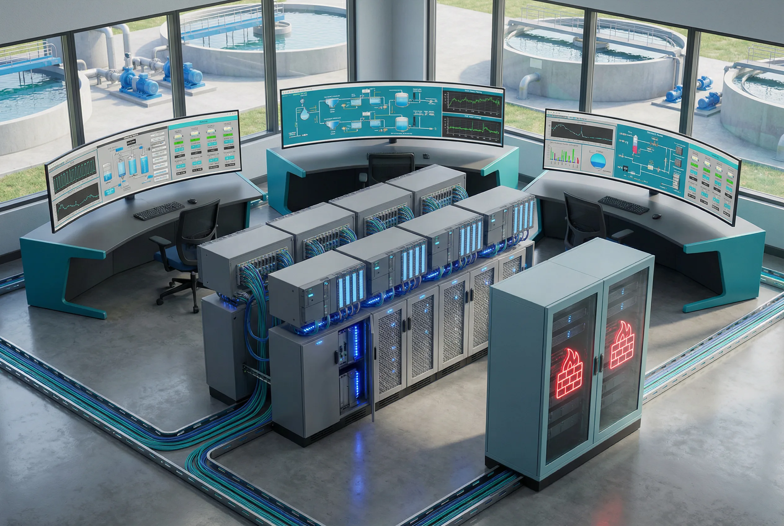
Figure 3.4: Water Treatment — SCADA control room with operator workstations showing process diagrams, PLC panels for pump/valve control, RTUs for distributed pump stations, industrial network switches, and DMZ cabinet with dual firewalls.
Water and wastewater treatment plants operate critical public health infrastructure. SCADA systems control chemical dosing, pump operations, filtration processes, and distribution network pressure. Distributed pump stations are connected via WAN links using RTUs and DNP3 or Modbus protocols. The primary threat scenario is unauthorized modification of chemical dosing setpoints, which could have immediate public health consequences. The design must enforce strict command-level whitelisting on all control paths and provide anomaly detection for setpoint changes outside normal operating ranges.
Key Design Considerations: DNP3 DPI must enforce read-only access for all IT-side queries — write commands must never originate from the IT domain. Remote pump station RTU communications must use encrypted WAN links (IPSec or TLS) with certificate-based authentication. The IDS must be configured with specific signatures for anomalous setpoint changes and unusual polling patterns. Emergency shutdown procedures must be tested to ensure they function correctly even when the DMZ is isolated.
3.6 Scenario 5: Rail Transit
S5 — Rail Transit Signaling and Auxiliary Control
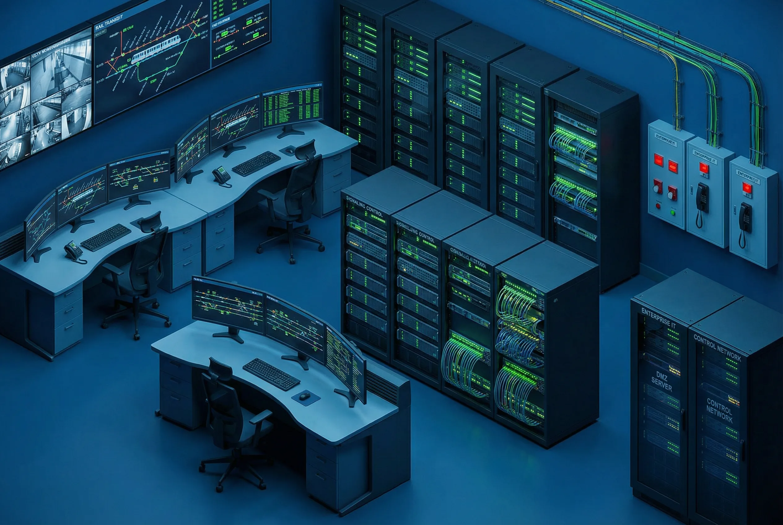
Figure 3.5: Rail Transit — Operations control center with train position maps, signaling status displays, interlocking system servers, communication equipment racks, CCTV monitoring wall, and DMZ server cabinet with dual firewalls.
Rail transit systems operate safety-critical signaling and train control systems alongside auxiliary systems including CCTV, passenger information, and station management. The signaling network (ATP/ATO/ATS) must be physically isolated from all other networks, including the auxiliary control network. The auxiliary control network may be logically isolated from the enterprise IT network using a DMZ. The primary design challenge is managing the boundary between the safety-critical signaling domain and the non-safety auxiliary domain, while also providing controlled data export for operational analytics and passenger information systems.
Key Design Considerations: The ATP/ATO/ATS signaling network must never be connected to any IP network — physical air gap is mandatory. The auxiliary control network DMZ must use separate physical firewalls from any corporate IT firewalls. CCTV video export to the enterprise network must use a unidirectional gateway to prevent any inbound path to the CCTV network. Passenger information system updates must flow through the file transfer gateway with content scanning.
3.7 Scenario 6: Oil and Gas Pipeline
S6 — Oil and Gas Pipeline SCADA
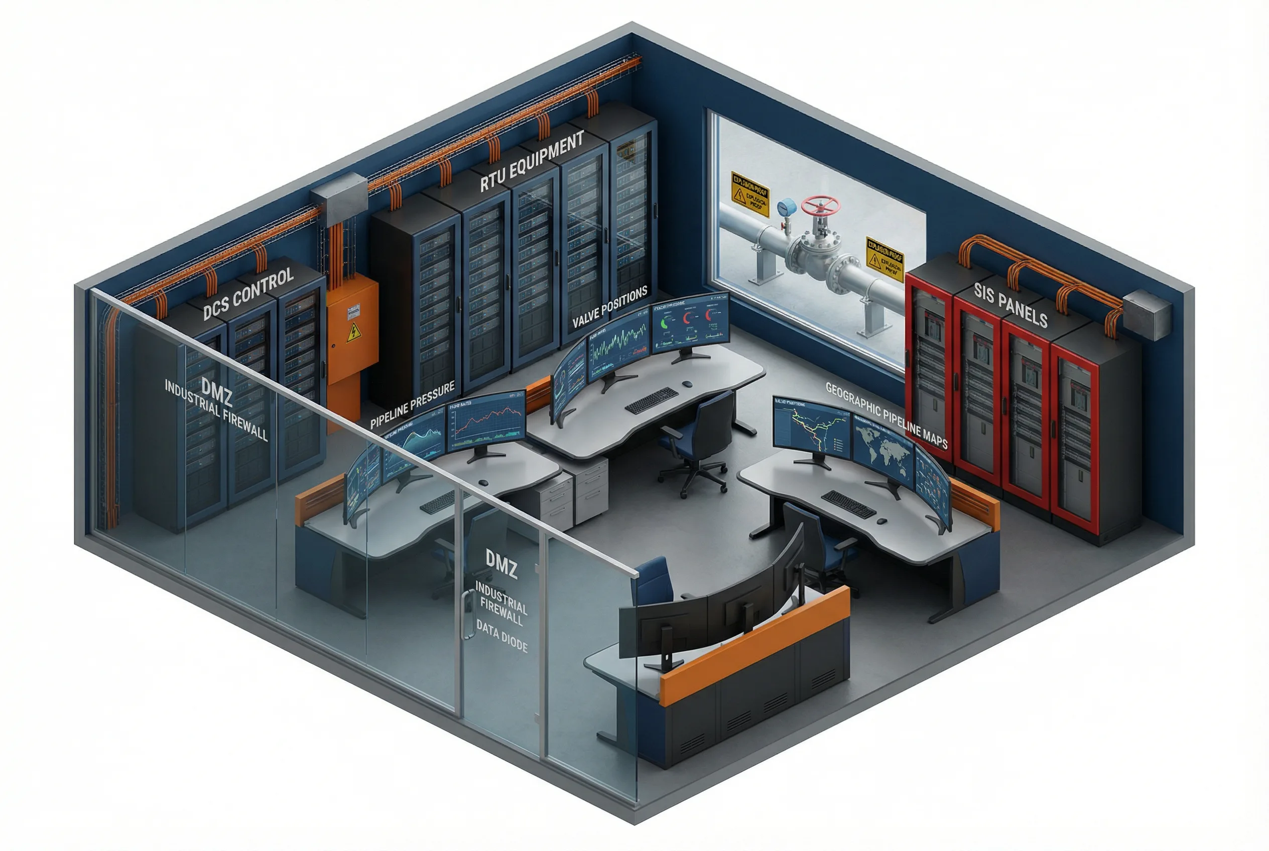
Figure 3.6: Oil and Gas Pipeline — SCADA control room with pipeline pressure/flow/valve monitoring, DCS control cabinets, RTU equipment, Safety Instrumented System (SIS) panels (physically separated), and DMZ cabinet with industrial firewalls and data diode equipment.
Oil and gas pipeline operations involve geographically distributed control systems managing compressor stations, pump stations, valve manifolds, and metering points. The Safety Instrumented System (SIS) must be physically and logically separated from the Basic Process Control System (BPCS) — this is a fundamental requirement of IEC 61511. The SCADA system communicates with remote RTUs via encrypted WAN links. The primary threat scenario is unauthorized valve closure or pump shutdown, which could cause pipeline overpressure events. Data diodes are strongly recommended for the telemetry export path, and all remote access must be channeled through a dedicated O&M zone with JIT approvals.
Key Design Considerations: The SIS network must have no electronic connection to the BPCS or IT networks — physical separation with documented air gap verification is required. The data diode placement must be validated to ensure no reverse path exists. All remote access to SCADA must require dual-person authorization for any write operations. The incident response runbook must include a pipeline isolation procedure that can be executed within 15 minutes of a confirmed cyber incident.
3.8 Scenario 7: Pharmaceutical Manufacturing
S7 — Pharmaceutical Manufacturing DCS
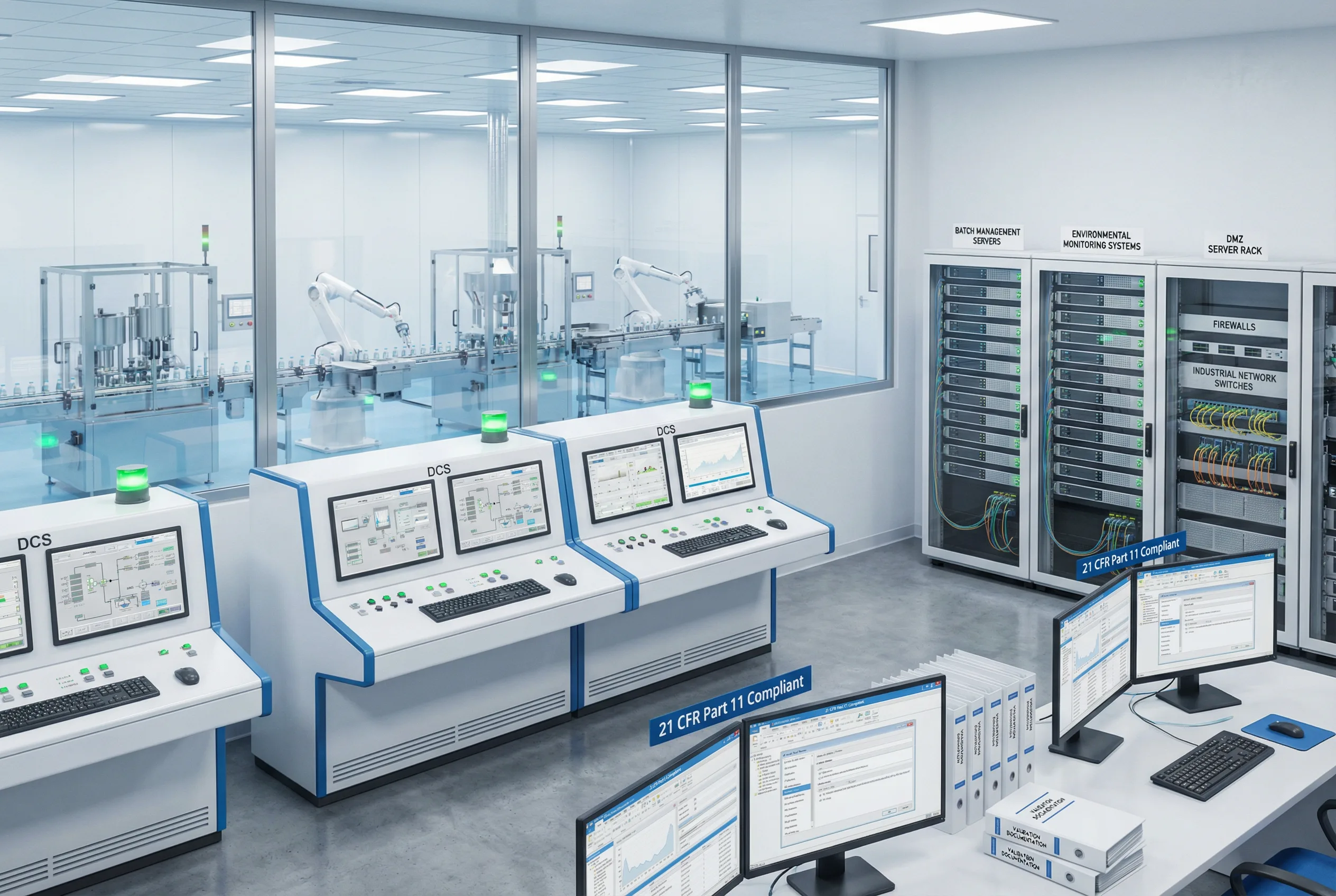
Figure 3.7: Pharmaceutical Manufacturing — Clean room with automated filling/packaging lines visible through glass, DCS control panels, batch management servers, environmental monitoring systems, 21 CFR Part 11 compliant workstations, and DMZ server rack with firewalls.
Pharmaceutical manufacturing environments operate under strict regulatory requirements including FDA 21 CFR Part 11, EU Annex 11, and GMP guidelines. The DCS controls batch processes, environmental monitoring, and automated filling/packaging lines. Every change to the control system configuration must be documented in an audit trail, and the system must maintain data integrity for regulatory submissions. The primary design challenge is balancing the strict change control requirements with the need for timely security patches and the integration of batch data with enterprise ERP and quality management systems.
Key Design Considerations: All firewall rule changes must be documented in the validation system with electronic signatures. The batch data export interface must be validated as part of the computer system validation (CSV) process. Patch management must follow a validated change control procedure with documented rollback capability. Environmental monitoring data (temperature, humidity, differential pressure) must be exported to the quality management system through a validated interface in the DMZ.
3.9 Scenario 8: Data Center Facility Management
S8 — Data Center Facility Management and Monitoring
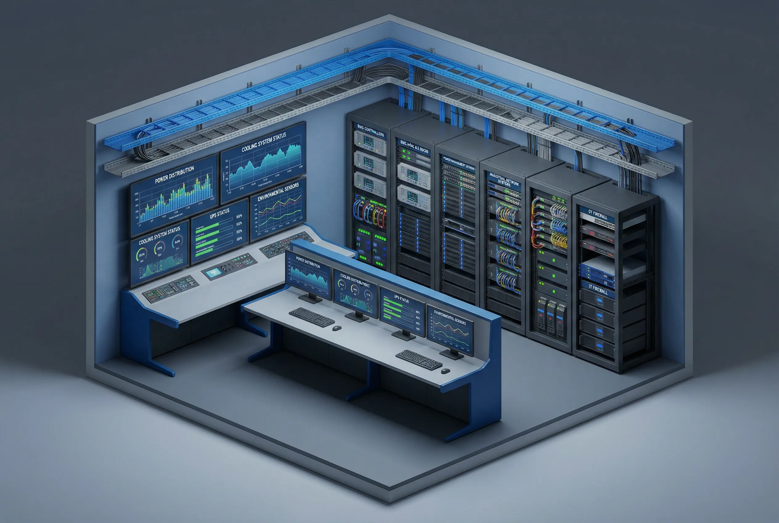
Figure 3.8: Data Center Facility Management — Monitoring room with power distribution, cooling system status, UPS status, and environmental sensor displays. BMS controllers, DCIM servers, power management systems, industrial network switches, and DMZ rack with firewalls separating facility OT from IT network.
Data center facility management systems control power distribution (PDUs, UPS, generators), cooling (CRAC/CRAH, chillers), and environmental monitoring. These systems are increasingly connected to DCIM (Data Center Infrastructure Management) platforms that integrate with IT service management tools. The primary security concern is that a compromise of the facility management network could allow an attacker to manipulate power or cooling systems, causing a service outage. The design must ensure that the DCIM integration path does not create a route from the IT network to the facility control systems.
Key Design Considerations: The DCIM integration must use a read-only API exposed in the DMZ — no write access from the IT network to facility control systems. Power and cooling monitoring data should be exported via a unidirectional gateway where possible. Generator and UPS control systems must be on a separate VLAN with the most restrictive access policy. Emergency power-off (EPO) systems must have physical controls that cannot be triggered remotely through the network. Cooling system control must be protected against unauthorized setpoint changes that could cause thermal events.