Installation & Debugging
Chapter 11 — Site preparation, physical installation requirements, commissioning procedures, and debugging guidance for OT/IT network segmentation systems
11.1 Installation Requirements
Successful installation of an OT/IT network segmentation system begins with thorough site preparation. The installation environment must meet specific physical, electrical, and environmental requirements to ensure reliable long-term operation. The photograph below shows a compliant installation in progress, illustrating the key requirements: proper clearance space, color-coded cable routing, grounding, environmental monitoring, and the presence of safety equipment. These requirements apply to all industrial environments, with additional considerations for hazardous areas (ATEX/IECEx zones).
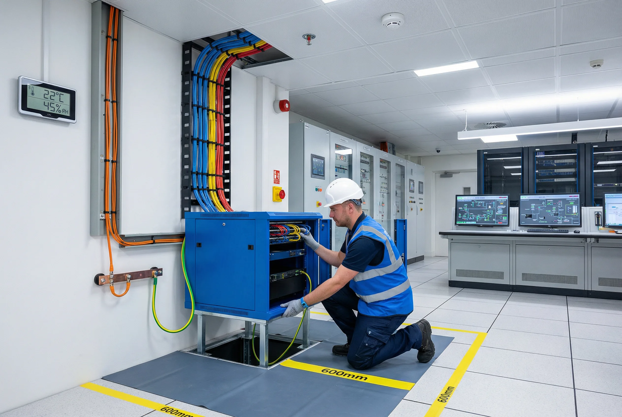
Figure 11.1: Installation Requirements — A technician in blue safety vest and hard hat installing an industrial DMZ cabinet (blue) in a modern control room. Key installation elements visible: color-coded cables (blue/orange/yellow) routed through wall cable management, green/yellow grounding cable connected to building ground bus, 600mm clearance zones marked with yellow tape, temperature/humidity monitor (22°C/45%RH), ESD mat, fire suppression system, and SCADA workstations in background. All installation requirements are demonstrated in a real industrial control room environment.
| Requirement Category | Parameter | Specification | Measurement Method |
|---|---|---|---|
| Environmental | Operating Temperature | 0°C to +50°C (industrial grade); 10°C to 40°C (standard) | Calibrated thermometer |
| Relative Humidity | 5% to 95% non-condensing | Calibrated hygrometer | |
| Altitude | 0 to 2000m (standard); derate above 2000m | GPS/altimeter | |
| Vibration | IEC 60068-2-6: 5–150Hz, 1g (DIN rail); 0.5g (rack) | Vibration meter during installation | |
| Electrical | Power Supply | 100–240VAC ±10%, 47–63Hz; or 24VDC ±20% (DIN rail) | Multimeter |
| Grounding | Protective earth <1Ω to building ground bus | Multimeter (resistance mode) | |
| Power Redundancy | Dual PSU with independent feeds from different UPS circuits | Visual inspection + failover test | |
| Physical Space | Front Clearance | Minimum 600mm (IEC 60950) | Tape measure |
| Rear Clearance | Minimum 600mm for cable management | Tape measure | |
| Side Clearance | Minimum 100mm for airflow | Tape measure | |
| Cable Routing | IT/OT Separation | Separate cable trays for IT (blue), OT (orange), Management (yellow) | Visual inspection |
| Fiber Bend Radius | Minimum 30mm (OS2 SM fiber) | Visual inspection | |
| Cable Length | Cat6: max 100m; OM3 fiber: max 300m; OS2 fiber: max 10km | Cable tester / OTDR |
11.2 Commissioning Sequence
The commissioning sequence must be followed in strict order to ensure that each layer of the system is verified before the next layer is configured. Skipping steps or commissioning out of sequence is a common cause of commissioning failures and security misconfigurations. The sequence below reflects the correct order for a standard Industrial DMZ deployment with HA firewalls and managed switches.
| Step | Activity | Verification | Estimated Duration |
|---|---|---|---|
| 1 | Physical installation: rack mounting, cable routing, grounding | Visual inspection, cable test, grounding test | 4–8 hours |
| 2 | Power-on and initial hardware verification: all LEDs, console access | Console login, hardware status check | 1–2 hours |
| 3 | Baseline configuration: hostname, management IP, NTP, syslog, SNMP | Ping management IP, verify NTP sync, verify syslog receipt | 2–4 hours |
| 4 | VLAN and switching configuration: VLANs, trunk ports, access ports, STP | VLAN membership test, STP topology verification | 2–4 hours |
| 5 | Firewall zone and interface configuration: zones, interfaces, routing | Interface status, routing table verification | 2–4 hours |
| 6 | Firewall security policy configuration: zone rules, NAT, application control, DPI | Policy test (permit/deny), application identification test | 4–8 hours |
| 7 | DMZ service configuration: historian relay, file gateway, syslog collector, NTP relay | End-to-end service test for each DMZ service | 4–8 hours |
| 8 | HA configuration and failover testing: HA pairing, sync verification, failover test | HA sync status, failover time measurement (<30s) | 2–4 hours |
| 9 | Remote access configuration: VPN, MFA, PAM, bastion host | End-to-end remote access test with MFA, session recording verification | 4–8 hours |
| 10 | OT IDS deployment and baseline: sensor placement, traffic capture, baseline learning | IDS alert generation for test events, baseline period (7–14 days) | 1–2 days |
| 11 | Full acceptance testing per Chapter 10 checklist | All acceptance test phases pass | 1–2 days |
| 12 | Documentation completion: as-built diagrams, configuration backup, handover | Documentation review and sign-off | 4–8 hours |
11.3 Common Commissioning Issues and Troubleshooting
The following table documents the most frequently encountered commissioning issues, their root causes, and the recommended troubleshooting steps. This reference is intended for use by commissioning engineers during the installation and debugging phase. Each issue is categorized by the commissioning step in which it typically occurs, enabling rapid diagnosis.
| Issue | Symptom | Root Cause | Troubleshooting Steps |
|---|---|---|---|
| OT device cannot reach historian relay | Historian data not updating; OT device shows connection timeout | Firewall rule missing or incorrect destination IP/port | 1. Check firewall policy log for denied traffic. 2. Verify source/destination IP and port. 3. Check routing table on OT switch. 4. Verify historian relay service is running. |
| HA failover takes >30 seconds | Traffic interruption during failover test exceeds 30s | HA heartbeat interface not on dedicated link; session sync not configured | 1. Verify HA heartbeat on dedicated interface (not data interface). 2. Enable session synchronization. 3. Reduce HA hello interval. 4. Re-run failover test. |
| OT IDS generating excessive false positives | IDS alert storm; SOC overwhelmed with low-priority alerts | IDS not tuned to OT environment; baseline not completed | 1. Verify IDS baseline period completed (7+ days). 2. Review and suppress known-good OT protocol patterns. 3. Tune alert thresholds for OT-specific protocols. 4. Engage IDS vendor for OT profile tuning. |
| Remote access VPN connects but cannot reach OT systems | VPN tunnel established; ping to OT devices fails | Split tunneling misconfiguration; firewall rule missing for VPN source IP | 1. Check VPN client routing table. 2. Verify firewall rule permits VPN source IP to bastion host. 3. Verify bastion host can reach target OT systems. 4. Check PAM access policy. |
| NTP synchronization failing on OT devices | OT devices showing incorrect time; SIEM event timestamps misaligned | NTP relay in DMZ not reachable from OT devices; firewall blocking UDP 123 | 1. Verify firewall permits UDP 123 from OT devices to DMZ NTP relay. 2. Verify DMZ NTP relay is synchronized to upstream NTP. 3. Check OT device NTP configuration (correct server IP). |