Architecture Design
Chapter 4 — Typical system topologies, zone definitions, data flow design, and physical wiring guidance for OT/IT network segmentation
4.1 Reference Architecture Overview
The OT/IT network segmentation reference architecture is structured around the Purdue Enterprise Reference Architecture (PERA) model, extended with modern security zone concepts from IEC 62443 and NIST SP 800-82. The architecture defines six functional zones arranged in a hierarchical topology, with controlled communication paths between adjacent zones and strictly prohibited direct connections between non-adjacent zones. The Industrial DMZ is the central enforcement point, hosting all services that mediate communication between the OT domain and the IT domain.
The reference architecture is designed to be modular and scalable. Smaller deployments may combine the O&M Access Zone with the Industrial DMZ, while larger deployments may further subdivide the Control Zone into separate zones for different process areas or safety integrity levels. The core principle — that no direct path exists between the IT domain and the OT Core or Control Zone — must be maintained regardless of the deployment scale.
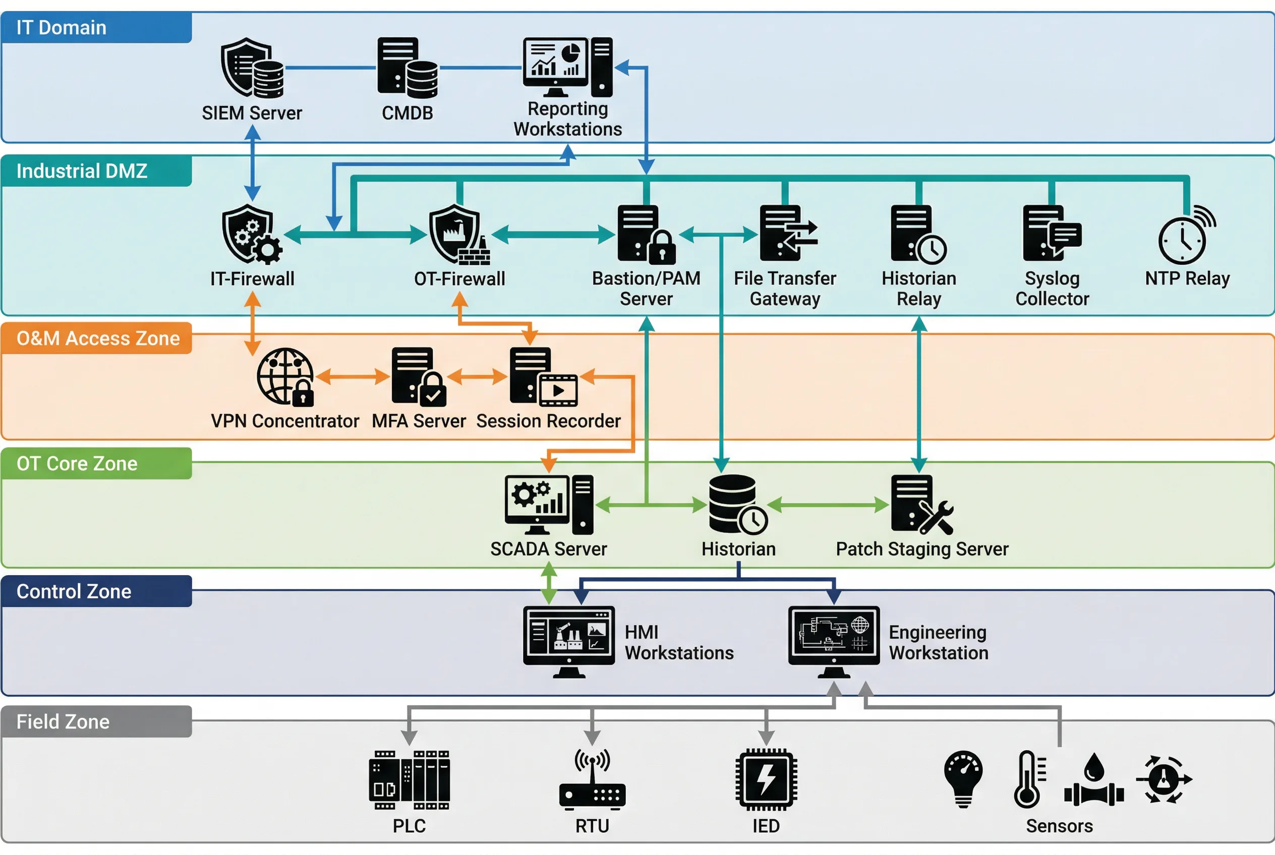
Figure 4.1: Typical OT/IT Network Segmentation Topology — Six-zone hierarchical architecture showing IT Domain, Industrial DMZ, O&M Access Zone, OT Core Zone, Control Zone, and Field Zone with all inter-zone communication paths and key devices.
| Zone | Purdue Level | Key Systems | Inbound from | Outbound to | Protocol Inspection |
|---|---|---|---|---|---|
| IT Domain | Level 4–5 | SIEM, CMDB, ERP, Reporting | Internet (via IT FW) | Industrial DMZ only | Standard IT FW/IPS |
| Industrial DMZ | Level 3.5 | IT-FW, OT-FW, Bastion, Historian Relay, File GW, NTP Relay | IT Domain, O&M Zone | IT Domain, OT Core | DPI + OT Protocol Inspection |
| O&M Access Zone | Level 3.5 | VPN Concentrator, MFA Server, Session Recorder | Internet (vendors/staff) | Industrial DMZ (Bastion) | VPN + MFA enforcement |
| OT Core Zone | Level 3 | SCADA Server, Historian, Patch Staging | Industrial DMZ only | Control Zone, Industrial DMZ | OT Protocol Whitelist |
| Control Zone | Level 2 | HMI Workstations, Engineering WS | OT Core Zone only | Field Zone, OT Core Zone | Industrial Protocol DPI |
| Field Zone | Level 0–1 | PLCs, RTUs, IEDs, Sensors, Actuators | Control Zone only | Control Zone only | Physical/L2 isolation |
4.2 Zone-to-Zone Communication Rules
The fundamental rule of the reference architecture is that communication between zones must be explicitly permitted — all traffic is denied by default. Each inter-zone boundary is enforced by a dedicated security control (firewall, data diode, or application gateway), and the permitted communication flows are defined by a zone communication matrix. The matrix specifies the permitted source zone, destination zone, protocol, port, and directionality for each allowed flow.
| Source Zone | Destination Zone | Permitted Protocols | Direction | Enforcement Device | Notes |
|---|---|---|---|---|---|
| IT Domain | Industrial DMZ | HTTPS (443), Syslog (514/TCP), NTP (123/UDP) | Bidirectional (restricted) | IT Firewall | IT FW rules enforced; no OT protocols |
| Industrial DMZ | OT Core Zone | OPC UA (4840), Syslog, NTP, RDP (via Bastion) | Bidirectional (restricted) | OT Firewall | DPI on OPC UA; no raw Modbus/DNP3 |
| O&M Access Zone | Industrial DMZ (Bastion) | RDP (3389), SSH (22) | Inbound to Bastion only | VPN + OT Firewall | MFA required; session recorded |
| OT Core Zone | Control Zone | OPC DA/UA, Modbus TCP, PROFINET | Bidirectional (restricted) | OT Managed Switch + ACL | VLAN separation; L3 ACL enforcement |
| Control Zone | Field Zone | PROFINET, EtherNet/IP, Modbus RTU, IEC 61850 | Bidirectional | Industrial Switch + VLAN | L2 isolation; no routing to OT Core |
| Any Zone | Non-adjacent Zone | None | Prohibited | Firewall deny-all | Violation triggers alert |
4.3 Industrial DMZ Detailed Design
The Industrial DMZ is the most complex zone in the architecture, hosting multiple security services that each serve a specific mediation function. The DMZ is bounded by two separate firewalls: the IT Firewall (facing the IT domain) and the OT Firewall (facing the OT Core Zone). These two firewalls must be from different vendors or product lines to prevent a single vulnerability from compromising both boundaries simultaneously — this is the dual-vendor firewall principle recommended by IEC 62443-3-3.
Within the DMZ, the following services are deployed on dedicated, hardened servers or appliances. Each service has a defined and limited communication scope — no DMZ service should have broader network access than required for its specific function. The principle of least privilege applies to all DMZ service accounts, firewall rules, and network access controls.
| DMZ Service | Function | IT-Side Ports | OT-Side Ports | Hardening Requirements |
|---|---|---|---|---|
| Bastion / PAM Server | Privileged access mediation for all remote O&M sessions | RDP/SSH from O&M Zone | RDP/SSH to OT Core/Control | MFA, session recording, JIT access, credential vault |
| Historian Relay | One-way data export of process data to IT historian/ERP | OPC UA / REST API to IT | OPC UA / OPC DA from OT Historian | Read-only OT connection; no write-back path |
| File Transfer Gateway | Controlled file transfer with content scanning | SFTP/HTTPS from IT | SFTP to OT Patch Staging | AV scan, file type whitelist, size limit, audit log |
| NTP Relay | Time synchronization relay from IT NTP to OT devices | NTP client from IT NTP | NTP server to OT devices | Stratum 1/2 source; no other traffic |
| Syslog Collector | Aggregate OT security logs for forwarding to SIEM | Syslog/CEF to IT SIEM | Syslog from OT devices | Log integrity; no command path to OT |
| DNS Relay | Controlled DNS resolution for OT devices | DNS queries to IT DNS | DNS server to OT devices | Whitelist-only resolution; no recursive queries to internet |
4.4 Physical Wiring and Cabinet Design
The physical implementation of the zone architecture requires careful attention to cable management, port labeling, and physical access controls. Color-coded cabling is strongly recommended to visually distinguish between network zones and reduce the risk of incorrect connections during installation or maintenance. The standard color coding used in this guide assigns blue cables to the IT network, orange cables to the OT network, yellow cables to the management network, and green cables to fiber optic connections.

Figure 4.2: Industrial DMZ Cabinet Wiring — Rack-mount cabinet showing IT-FW, OT-FW, DMZ Switch, OT Switch, patch panels, and Bastion Server with color-coded cables: blue (IT), orange (OT), yellow (management), green (fiber). DIN rail section shows field-side industrial equipment.
| Cable Color | Network Zone | Typical Connections | Connector Type |
|---|---|---|---|
| Blue | IT Network | IT FW to IT Switch, IT Switch to IT servers | RJ45 Cat6/6A |
| Orange | OT Network | OT FW to OT Switch, OT Switch to SCADA/HMI | RJ45 Cat6/6A |
| Yellow | Management Network | OOB management ports, console servers | RJ45 Cat5e/6 |
| Green | Fiber (Backbone) | Inter-cabinet fiber, long-distance OT links | LC/SC Duplex |
| Gray | Serial / Console | Console cables, RS-232/485 serial links | DB9, RJ45 rollover |
4.4.1 Cabinet Layout Recommendations
The DMZ cabinet should be organized from top to bottom in the following order: patch panels (top), IT Firewall, DMZ Switch, OT Firewall, OT Switch, Bastion Server, and power distribution units (bottom). This arrangement minimizes cable crossing between zones and makes the zone boundary visually clear. The IT-side and OT-side patch panels should be physically separated — either in different sections of the same cabinet or in separate cabinets — to prevent accidental cross-connections.
- Cabinet must be lockable with access logging (electronic lock preferred)
- Separate cable management trays for IT-side and OT-side cables
- All ports not in use must be physically blanked with port blockers
- Console access to all devices must be available via an out-of-band console server
- Power feeds for IT-side and OT-side equipment should be from separate UPS circuits
- Temperature and humidity monitoring sensors must be installed in the cabinet
4.5 High Availability and Redundancy Design
Critical OT environments require that the network segmentation infrastructure itself does not become a single point of failure. The reference architecture supports active-passive or active-active high availability configurations for the firewall pairs and key DMZ services. The HA design must be carefully validated to ensure that the failover process does not create a temporary security gap — specifically, the HA synchronization channel between firewall peers must be on a dedicated, isolated management network and must not carry production traffic.
| Component | HA Mode | Failover Time | State Sync | Notes |
|---|---|---|---|---|
| IT Firewall | Active-Passive | <30 seconds | Session state, rules | Dedicated HA sync link required |
| OT Firewall | Active-Passive | <30 seconds | Session state, rules | Dedicated HA sync link required |
| DMZ Switch | Stacked or LACP | <1 second (LACP) | VLAN, STP state | Spanning Tree must be configured |
| Bastion Server | Active-Passive (cluster) | <60 seconds | Session database | Active sessions may be interrupted on failover |
| Historian Relay | Active-Passive | <60 seconds | Buffer queue | Buffered data replayed after failover |
| NTP Relay | Dual independent servers | Immediate (DNS round-robin) | N/A | OT devices should have two NTP servers configured |